The Mitsubishi fuel pump is a known weakness on an otherwise FANTASTIC machine. The points burn away due to arcing.
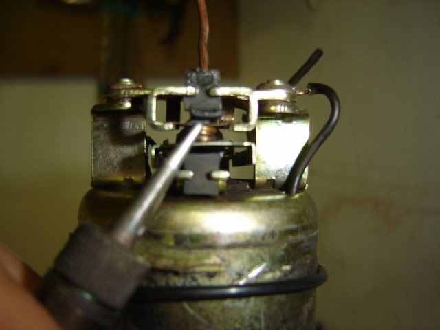
1st the 2c bush repair. Glue a piece of placstic between the rubber buffer and the "top" of the point, as pointed to here with the soldering iron. This should get you home (I did 6000km on such a jimmey)
The next bit is a R 6.00 fix for a R 2 000.00 job. It is a variation of ridewestKTM which I found on https://www.ktm950.info/how/fuel_pump/mitsubishi/rideswestktm_mitsubishi.html
I take no credit for it nor can I guarantee anything, I have done 3 pumps so far, and am currently riding with one on my bike and at the price it is definately worth it!!!
I also made some spelling mistakes on the photos and called the 15 k ohm resistor a 15 ohm resistor, that will have to stay as it is otherwise I will never post this.
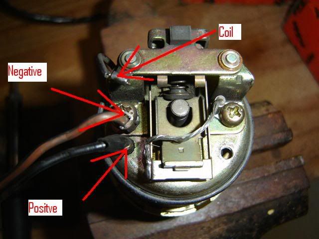
Here is a photo of the stock pump showing the basics
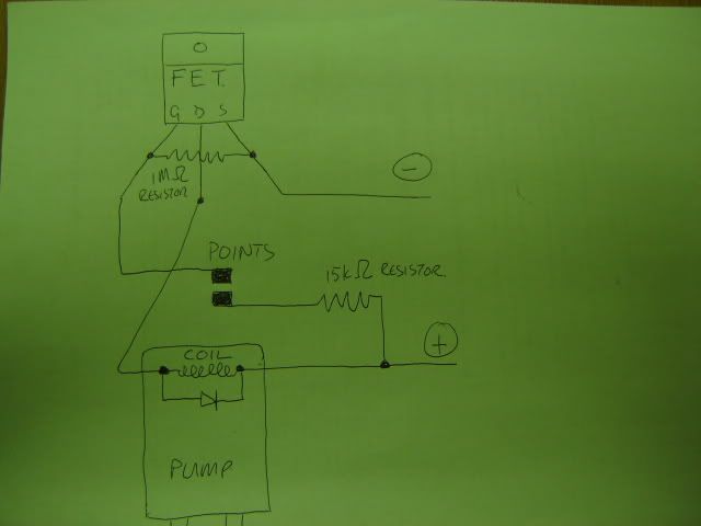
You need to get an FET (or MOSFET) IRFZ44; a 15 k ohm resistor and a 1 M ohm resistor. I got mine from Mantech, but any electronics shop will have these.
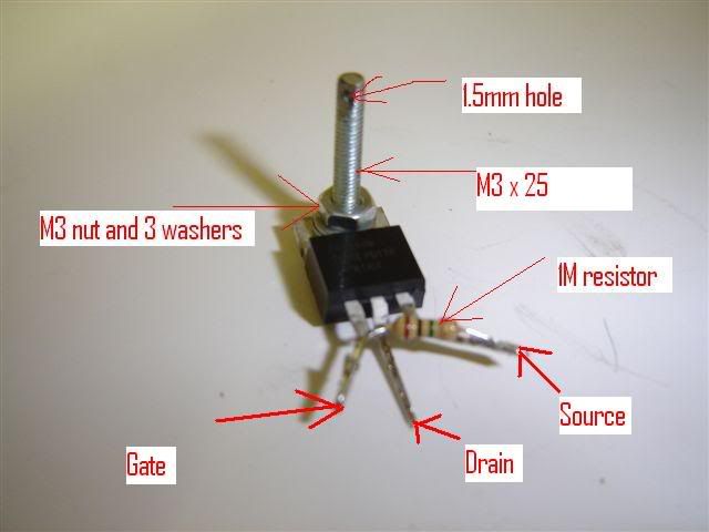
This diagram should help a bit as the photos are not very clear
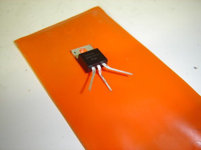
Bend the legs of the FET as shown
Solder the 1M to the Gate and Source legs. You need to fit an M3x25 bolt with 3 washers to the hole in the FET as you will use the bolt to fasten the FET to the pump cover. I drilled a 1.5mm hole through the bolt and used dental floss to help guide the bolt through the hole.
Next up, unsolder the coil wire and unscrew the Negative (the brown wire).
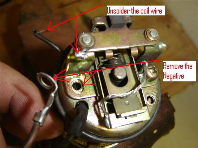
I didn't have any lugs, so I cut the lug off the negative wire and soldered one end of the 15 k ohm resistor to it.
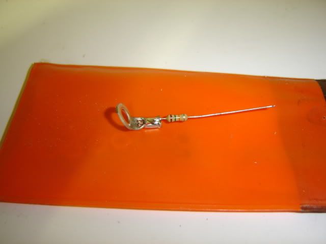
Now solder the Gate and 1M pin to the mounting where the coil wire was removed.
The coil wire gets soldered to the Drain pin of the FET, the photo was taken after I had already shrunk on some heat shrink.
I found the better way of joining the 15k ohm resistor to the + was to cut the positive. In fact I also cut the plug off and removed the protective sleeve so I could clean it and you need bare wire to test the pump. Solder the resistor to the + and insulate with heat shrink. Take note to solder in such a way that the wires will easily reach the opening in the cover (cap)
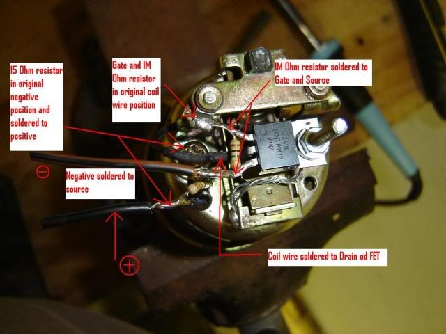
When you're done it should look something like this.
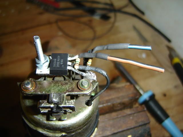
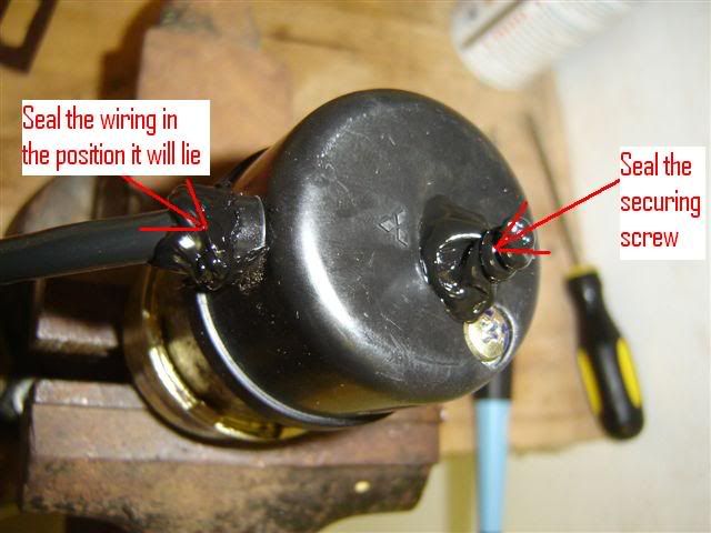
You need to estimate the position of the M3 bolt and drill a hole through the cap where the bolt goes through. Now use the dental floss to guide the bolt while pulling the wires through the rubber grommit in the cap. I fitted the grommit first and then fed the wires through, that is another reason why it is better to cut the plug off and solder them back afterwards.
I then used a 12V car battery charger to test the conversion, VOILA!!!
Seal the bolt and grommit with some silicone
1st the 2c bush repair. Glue a piece of placstic between the rubber buffer and the "top" of the point, as pointed to here with the soldering iron. This should get you home (I did 6000km on such a jimmey)

The next bit is a R 6.00 fix for a R 2 000.00 job. It is a variation of ridewestKTM which I found on https://www.ktm950.info/how/fuel_pump/mitsubishi/rideswestktm_mitsubishi.html
I take no credit for it nor can I guarantee anything, I have done 3 pumps so far, and am currently riding with one on my bike and at the price it is definately worth it!!!
I also made some spelling mistakes on the photos and called the 15 k ohm resistor a 15 ohm resistor, that will have to stay as it is otherwise I will never post this.
Here is a photo of the stock pump showing the basics

You need to get an FET (or MOSFET) IRFZ44; a 15 k ohm resistor and a 1 M ohm resistor. I got mine from Mantech, but any electronics shop will have these.
This diagram should help a bit as the photos are not very clear

Bend the legs of the FET as shown

Solder the 1M to the Gate and Source legs. You need to fit an M3x25 bolt with 3 washers to the hole in the FET as you will use the bolt to fasten the FET to the pump cover. I drilled a 1.5mm hole through the bolt and used dental floss to help guide the bolt through the hole.

Next up, unsolder the coil wire and unscrew the Negative (the brown wire).

I didn't have any lugs, so I cut the lug off the negative wire and soldered one end of the 15 k ohm resistor to it.

Now solder the Gate and 1M pin to the mounting where the coil wire was removed.
The coil wire gets soldered to the Drain pin of the FET, the photo was taken after I had already shrunk on some heat shrink.
I found the better way of joining the 15k ohm resistor to the + was to cut the positive. In fact I also cut the plug off and removed the protective sleeve so I could clean it and you need bare wire to test the pump. Solder the resistor to the + and insulate with heat shrink. Take note to solder in such a way that the wires will easily reach the opening in the cover (cap)

When you're done it should look something like this.

You need to estimate the position of the M3 bolt and drill a hole through the cap where the bolt goes through. Now use the dental floss to guide the bolt while pulling the wires through the rubber grommit in the cap. I fitted the grommit first and then fed the wires through, that is another reason why it is better to cut the plug off and solder them back afterwards.
I then used a 12V car battery charger to test the conversion, VOILA!!!
Seal the bolt and grommit with some silicone


